INSTALLATION CHECKLIST & TROUBLESHOOTING – Here’s some things to watch out for in your Rivet installation, or to try if you’re having trouble…
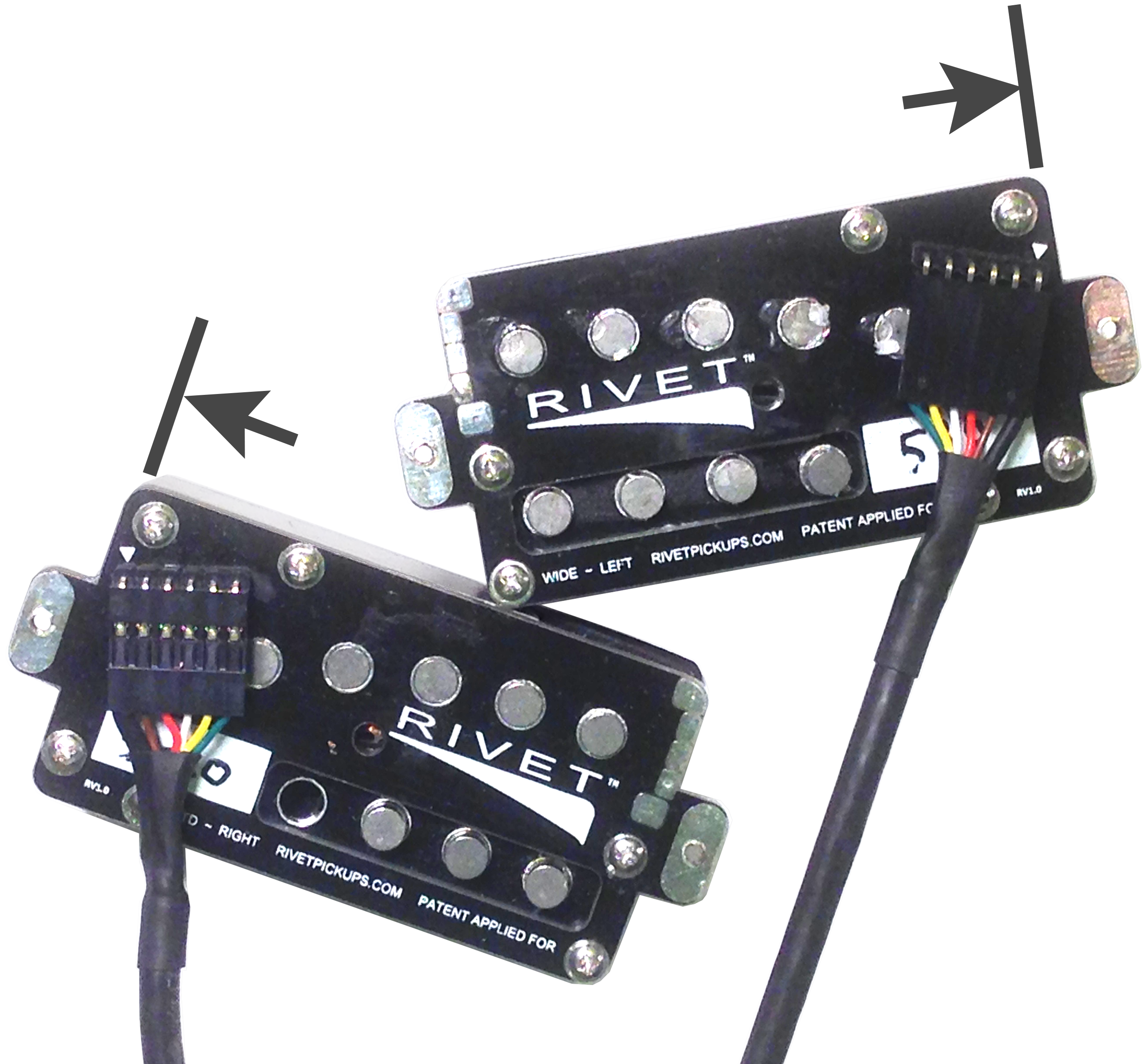
1. Make sure BLACK ground wires of the cables are oriented properly.
On the pickup, the black wire goes on the pin nearest the edge of the pickup. (It’s marked with the word “ground” and also a small white triangle.)
On the connector card, the black wire 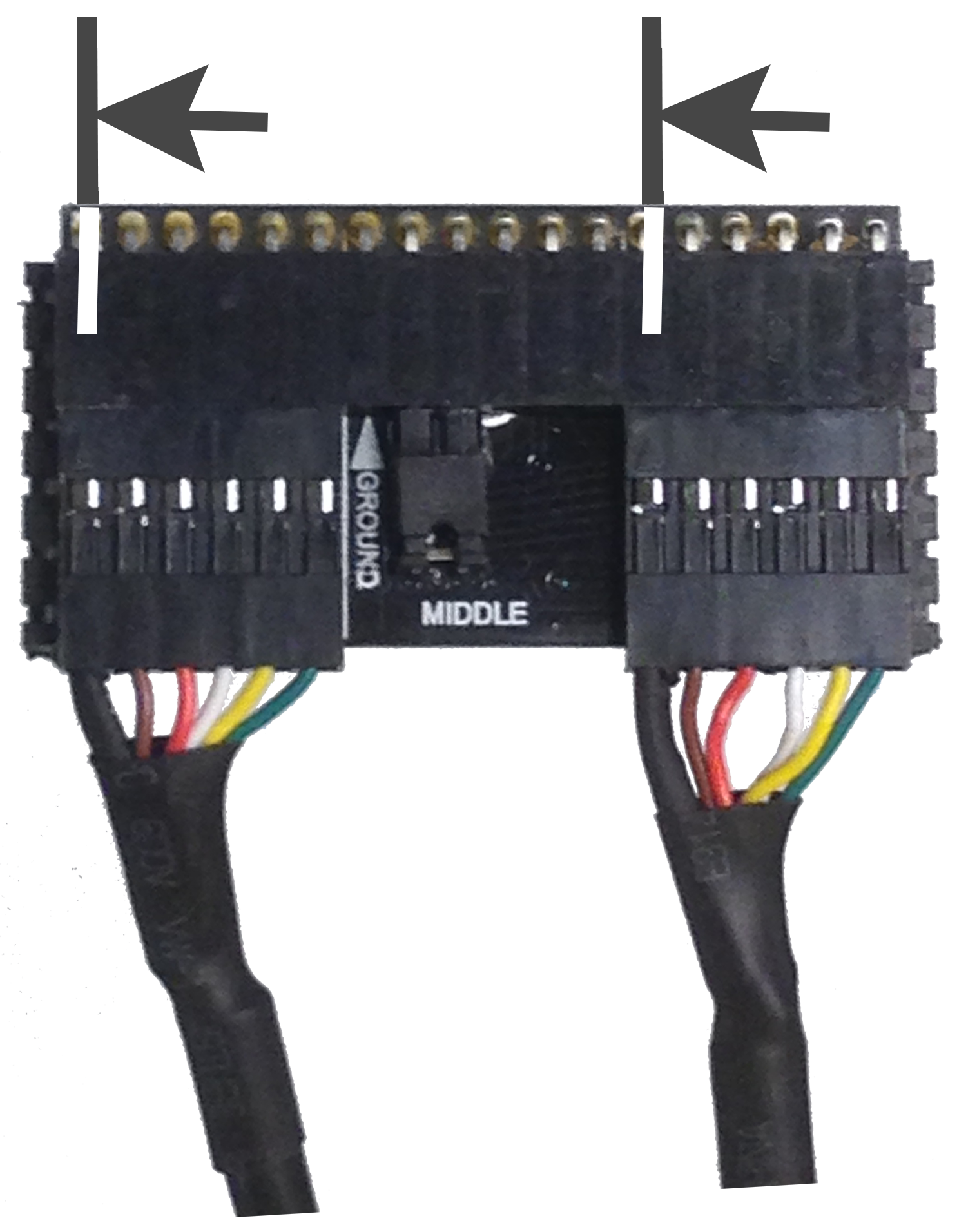 goes in the hole furthest to the left for each cable attached. (There’s a white triangle marking the ground hole for a couple of the positions.)
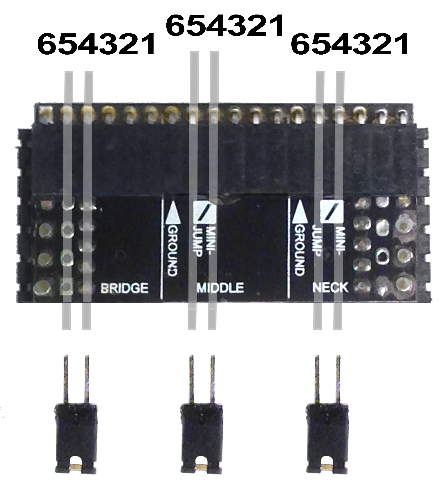
2. Make sure that in the back of the connector card you have a jumper inserted where ever there is NOT a Rivet cable plugged in.
Each empty cable position will have 6 pin holes, and should have a jumper in holes 5 & 4…
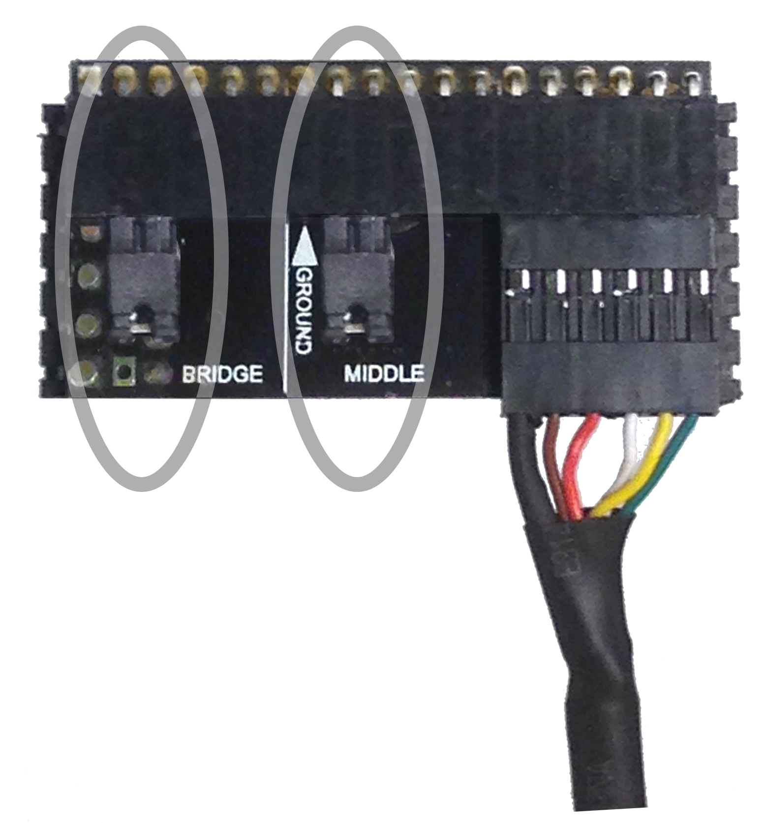
For example, if you have a pair of Rivets installed in the bridge and neck positions, then you should have one jumper in the middle position where there is no Rivet cable:

Or if you have only one Rivet installed, let’s say in the neck position, then you should have jumpers in the bridge and the middle positions where there are no Rivet cables:
3. Make sure there are no short circuits in these areas:
Under the pickups
Make sure no braided wire shielding is short circuiting against the screws and silver square patterns along the edge of the pickup opposite the connector pins. That area may be covered with black cloth tape for insulation.
In the control cavity…
Make sure no stray exposed wire or braided shield is contacting any of the pins of the connector card.
Make sure the connector card itself is not colliding with any solder lugs on pot or jacks, etc.
Make sure the exposed silver braided shielding of the cables is not touching any solder lugs on pots or jacks, etc.
4. Make sure the wire leads on the push~pull pot have not broken loose during installation.
5. Make sure the razor blade card is deeply seated in the slot it is fitted into. To confirm, remove the screw that holds it down and angle it up about 45 degrees, and it should become movable within the slot. Press it deeply in, evenly at both ends, and then push it down against the connector card and replace the screw. It should now be well seated.
6. If pickup output seems “bad”, try flipping the the razor blade card or swapping it with another card. Is only one of the sides (or cards) faulty?
7. If one of the pickups seems dead, try swapping the cables at the connector card. If the dead pickup becomes good (and good pickup becomes dead!), then the cable, connector card, or razor blade may be suspect. If the same pickup remains dead, remove it and test its ohm readings across the jumper pin combinations as in the next step.
8. Test the coil ohm readings with a multimeter:
Coil readings…
a) START to FINISH pins should read approximately 8K or so in ohms. (If the reading is zero the coil is shorted, if “open loop” the coil’s wire would seem to be broken.)
b) TAP to FINISH pins should read approximately 7K or so in ohms. (If the reading is zero the coil is shorted, if “open loop” the coil’s wire would seem to be broken.)
c) AUX START to AUX FINISH pins should read approximately 5K or 4K, or there about. (If the reading is zero the coil is shorted, if “open loop” the coil’s wire would seem to be broken.)
Ground test…
d) The GROUND pin should read “open loop” when measuring from it to any of the other pins. (If the reading is zero the pin is shorted, if an actual numeric value is measured then pin at the opposite end of that coil’s wire is shorted.)